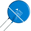
 What are PTC thermistors?
PTC stands for „Positive Temperature Coefficient“. PTC thermistors are resistors with a positive temperature coefficient, which means that the resistance increases with increasing temperature.
PTC thermistors are divided into two groups, based on the materials used, their structure and the manufacturing process. The first group of PTC thermistors is comprised of silistors, which use silicon as the semiconductive material. They are used as PTC temperature sensors for their linear characteristic. The second group is the switching type PTC thermistor. This type of PTC thermistors is widely used in PTC heaters, sensors etc. Polymer PTC thermistors, made of a special plastic, are also in this second group, often used as resettable fuses. The switching type PTC thermistor has a highly nonlinear resistance-temperature curve. When the switching type PTC thermistor is heated, the resistance starts to decrease at first, until a certain critical temperature is reached. As the temperature is further increased above that critical value, the resistance increases dramatically. This article will focus on the switching type PTC thermistors.
PTC thermistor definition
A PTC thermistor is a thermally sensitive resistor whose resistance increases significantly with temperature.
Characteristics of PTC thermistors
Switching PTC thermistors are usually made of poly-crystalline ceramic materials that are highly resistive in their original state and are made semi-conductive by the addition of dopants. They are mostly used as PTC self-regulating heaters. The transition temperature of most switched PTC thermistors is between 60°C and 120°C. However, there are special application devices manufactured that can switch as low as 0°C or as high as 200°C.
Silistors have a linear resistance-temperature characteristic, with a slope that is relatively small through most of their operational range. They may exhibit a negative temperature coefficient at temperatures above 150 °C. Silistors have temperature coefficients of resistance of about 0.7 to 0.8% °C.
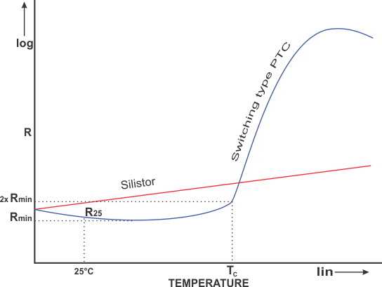
The resistance-temperature(R-T) characteristics of a PTC thermistor and a silistor
Transition temperature (Tc)
As can be seen from the figure, switching PTC thermistors have a slightly negative temperature coefficient up to the point of minimum resistance. Above this point, it experiences a slightly positive coefficient up to the moment it reaches it’s transition temperature – TC. This temperature is called the switch, transition or Curie temperature. The switch temperature is the temperature at which the resistance of switching type PTC thermistors starts to rise rapidly. The Curie temperature is most of the time defined as the temperature at which the resistance is twice the value of the minimum resistance.
Minimum resistance (Rmin)
The minimum resistance of a PTC thermistor is the lowest resistance that can be measured on a switched type PTC thermistor, as seen on the R-T curve. It is the point on the curve after which the temperature coefficient turns positive.
Rated resistance (R25)
The rated PTC resistance is normally defined as the resistance at 25°C. It serves to classify the thermistors according to their resistance value. It is measured with a low current that does not heat the thermistor enough to affect the measurement.
Dissipation constant
The dissipation constant represents the relationship between the applied power and the resulting body temperature increase due to self-heating. Some of the factors that affect the dissipation constant are: contact wire materials, the way the thermistor is mounted, ambient temperature, conduction or convection paths between the device and its surroundings, the size and even the shape of the device itself. The dissipation constant has a major impact on the self-heating properties of the thermistor.
Maximum rated current
The rated current represents the maximum current that can constantly flow through a PTC thermistor at specified ambient conditions. Its value depends on the dissipation constant and the R-T curve. If the thermistor is overloaded up to the point that the temperature coefficient starts to decline again, this will result in a runaway power situation and destruction of the thermistor.
Maximum rated voltage
Similarly to the maximum rated current, the maximum rated voltage represents the highest voltage that can be continuously applied to the thermistor at specified ambient conditions. Its value, too, depends on the dissipation constant and the R-T curve.
Modes of operation
Depending on the application, PTC thermistors can be used in two modes of operation; self-heated and sensing (also called zero-power).
Self-heated mode
Self-heated applications exploit the fact that when a voltage is applied to a thermistor and sufficient current flows through it, its temperature increases. As the Curie temperature is approached, the resistance increases dramatically, allowing much less current to flow. This behavior can be seen from the figure on the left. The resistance change near the Curie temperature can be several orders of magnitude within a temperature span of only a few degrees. If the voltage remains constant, the current will stabilize at a certain value as the thermistor reaches thermal equilibrium. The equilibrium temperature depends on the voltage applied, as well as the thermal dissipation factor of the thermistor. This mode of operation is often utilized when designing temperature dependent time delay circuits.
Sensing (zero-power) mode
In this mode of operation, the power consumption of the thermistor is so small that it has a negligible effect on the thermistor’s temperature and therefore resistance, in contrast to the self-heated mode. The sensing mode is usually used when measuring temperature using the R-T curve as a reference.
Construction and properties
Switching type PTC thermistors are made of poly-crystalline materials. They are often fabricated using mixtures of barium carbonate, titanium oxide and additives like tantalum, silica and manganese. The materials are ground, mixed, compressed into disks or rectangle shapes and sintered. Afterwards, contacts are added and they are finally coated or encased. The manufacturing process requires very careful control of materials and impurities. Contaminations on the order of a few parts per million can cause major changes in the thermal and electrical properties.
Polymer PTCs are made of a slice of plastic with carbon grains embedded in it. When the device is cool, the carbon grains are in close contact with each other, forming a conductive path through the device. As the device heats up, the plastic expands and the grains move further apart, raising the total resistance of the device.
Silistors rely on the bulk properties of doped silicon and exhibit resistance–temperature characteristics that are close to linear. They are produced from high pure quality silicon wafers, made in different shapes. The temperature-resistance curve depends on the amount of doping used.
Typical applications for PTC thermistors
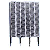
PTC air heater
Self-regulating heaters
If there is a current running through a switching PTC thermistor, it will auto-stabilize at a certain temperature. It means that if the temperature is decreased, the resistance will decrease as well, allowing more current to flow and thus heating the device. Similarly, if the temperature is increased, the resistance is increased as well, limiting the current passing through the device, thus cooling it down. The PTC thermistor has then reached a point where the power consumed is practically independent of the voltage over a relatively wide voltage range. These PTC thermistors are often made of ceramics in various shapes and sizes and because of their design flexibility, PTC ceramic heaters are a great choice for providing controlled electrical heat. For increased heat transfer, the ceramic heating elements can be mounted on aluminium heat sinks or grids.
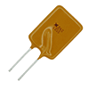
Polymer PTC fuse
Over-current protection
Switched PTC thermistors are used as over-current limiters or resettable fuses in various circuits. In the case of an over-current situation, the thermistor body temperature rises and quickly reaches the transition temperature. This results in the resistance of the PTC thermistor sharply rising, limiting current in the circuit. When the over-current or short-circuit situation is solved and the thermistor is cooled down again, the circuit will function as normal again. In this way it acts as a automatic resettable fuse. Normally polymer PTC thermistors are used for this application. They are known under different trade names such as polyfuse, polyswitch and multifuse.
Time delay
A time delay in a circuit can be provided using the time needed for a PTC thermistor to heat up enough to switch from its low resistance state to a high resistance state, and vice versa. The time delay is dependent upon the size, ambient temperature and the voltage it is connected to, as well as the circuit it is utilized in. An example of time delay use for PTC thermistors is their use in fluorescent lamps. When power is first applied, the thermistor is in a cold state (room temperature). The lamp voltage is below the ignition voltage and the current flowing through the circuit heats up the electrodes and the PTC at the same time. When the Curie temperature is reached, the PTC will switch, the voltage across the lamp will exceed the ignition voltage and the lamp will begin normal operation. Preheating of the electrodes extends lamp life significantly, which is why PTC thermistors are used in such circuits.
Motor starting
Some electrical motors have a separate startup winding which needs to be powered only during motor startup. In such cases, we may use the self-heating effect of a PTC thermistor connected in series with such a winding. When the circuit is turned on, the PTC thermistor has a low resistance, allowing current to pass through the startup winding. As the motor starts, the PTC thermistor heats up and at one point switches to a high resistance state. The time needed for this to occur is calculated based on the required motor startup time. Once heated up, the current through the PTC thermistor becomes negligible and this shuts off the startup winding current.
Liquid level sensing
These applications rely on the change in the dissipation constant when the conduction and convection heat transfer are increased. An increase in the dissipation constant, resulting from the contact between the device and a liquid or an increased air flow over the device will lower the thermistor’s operating temperature and increase the amount of power needed to maintain a given body temperature. The power increase can be measured and indicates to the system that the thermistor is, for example, immersed in a liquid.
PTC thermistor symbol
The following symbol is used for a positive temperature coefficient thermistor, according to the IEC standard.
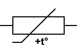
PTC thermistor symbol
IEC standard